Required Files and Assumptions
This part of the XTMF documentation assumes that the provided Frabitztown input files have already been downloaded and extracted.
- ZoneAttractions.csv
- A two-column CSV input file with the amount of attractions per zone.
- ZoneProductions.csv
- A two-column CSV input file listing the amount of trip productions per zone.
- Zones.csv
- A multi-column CSV input file total zone data for the Frabitztown network.
- ZeroDemandMatrix.311
- A simple .311 Emme matrix filled with all zero values.
- EMME_TransitLine_Aggregation.csv
- Transit line aggregation file for Emme.
- (Network Scenario Folder)
- Additional input required for Frabitztown.
- (Frabitztown Network)
- Emme project and data bank for Frabitztown.
Note
Frabitztown input files can be accessed at: http://tmg.utoronto.ca/doc/1.3/frabitztown.zip
Creating the Project
Once XTMF is opened click “New Project”. Enter Frabitztown as the project name and press enter. When the project is created, XTMF will automatically be redirected to the project page. The next step is to create a new model system that will be contained within the “Frabitztown” project.
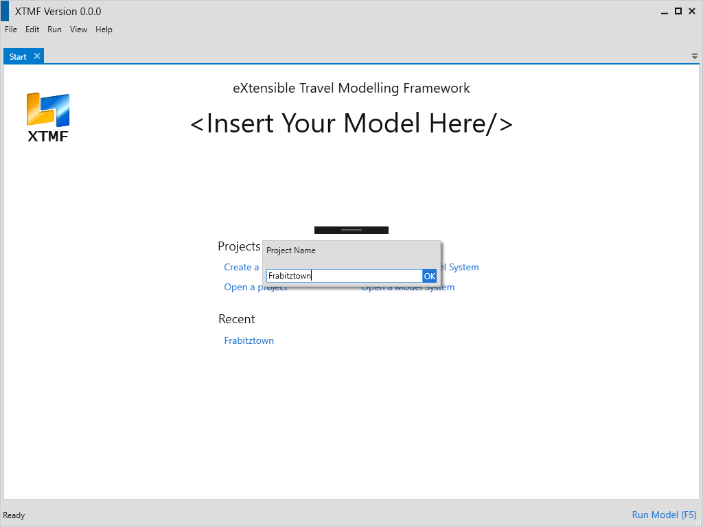
Entering a name for a new project.
At the bottom of the project page, click the button that is labelled “Create New Blank Model System”. Enter “Frabitztown” here again, or another name of your choosing. Once you have chosen a name, click “OK” or press enter. A new model system will appear on the left hand side of the project page. There will be a small disclaimer warning that the model system requires additional setup – this indicates that the model system is new and requires further setup to be in a runnable / complete state.
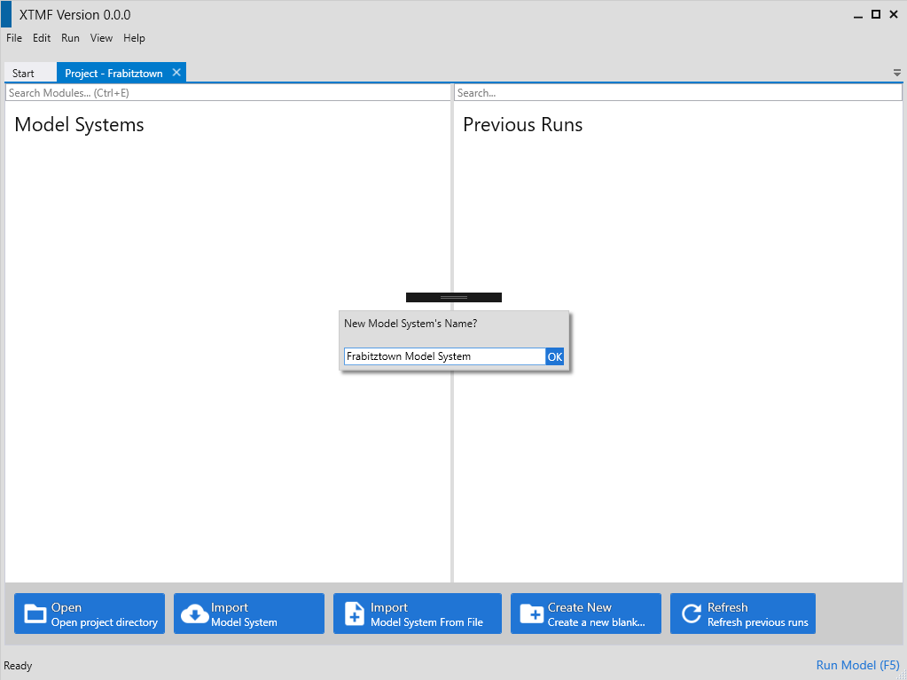
Entering a name for the new model system.
Starting the Frabitztown Model System Construction
With the Frabitztown project open in XTMF, double click the new Frabitztown model system that was made in the previous step. XTMF will now open the model system in a new tab / page.
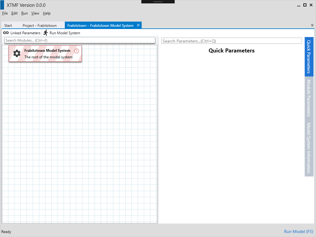
A blank model system.
The Frabitztown demo model system will make use of a module bundled as part of the main XTMF distribution. The module that will be used is called BasicTravelDemandModel. To make this the model system’ root module, select and right click the cell with the description “The root of the model system” and choose
“Set Module” from the context menu. A small dialog window will appear initially with a large list of modules that can serve as a “root” of a model system. Modules cannot be placed arbitrarily into model systems - only valid modules can be put into their proper slots. The list of modules shown are all those loaded by XTMF
that can be the root of a model system. The filter text box can be used to quickly find the module being looked for. In this case, enter the first few characters of “BasicTravelDemandModel” to find it quickly. Double click the module to finally set it to the root of the model system.
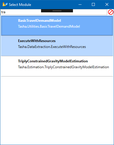
Choosing BasicTravelDemandModel from the ‘Select Module’ window.
Once the module type is chosen, the model system display will contain new items in the grid view. The BasicTravelDemandModel defines as its children 4 sections
of modules.
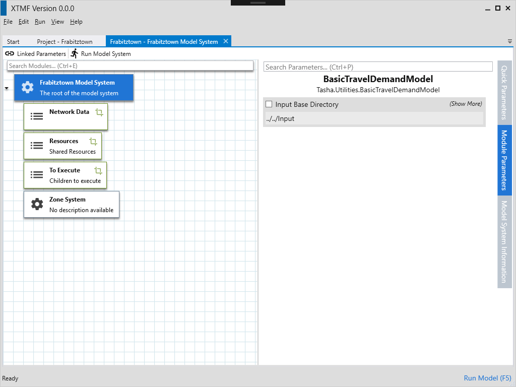
The root of the Frabitztown model system - (with BasicTravelDemandModel set as the root
module).
![graph foo {
graph [rankdir=LR];
"Basic Travel Demand Model"[shape=box];
"Network Data"[shape=box];
"To Execute"[shape=box];
"Resources"[shape=box];
"Basic Travel Demand Model" -- "Network Data";
"Basic Travel Demand Model" -- "Resources";
"Basic Travel Demand Model" -- "To Execute";
"Basic Travel Demand Model" -- "Zone System";
}](_images/graphviz-1d11fe466d61f3ae06c9d91afcac10eb43873db2.png)
Basic Travel Demand Model Modules
Network Data- An optional module, this can be left unassigned for the purpose of this guide.
Resources- A list of resources that can be shared for modules throughout the model system.
To Execute- A list of modules that will be executed with the model sytem is run.
Zone System- A module that loads in zonal data for the model system. This information is sometimes required and referenced from other modules.
Setting the Input Directory
Typically a relative input directory needs to be set for model systems. Specifying an input directory makes it easier to refer
to files that need to be read-in. To set the base input directory, click on the module with description “The root of the model system”. The right hand
panel of the model system page will have option to specify the input directory to use as a base for this BasicTravelDemandModel.
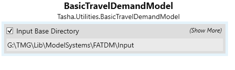
Choosing a base input directory from the root module parameter display.
This location should be pointed to the directory that contains the input contents for the model system.
Specifying the Zone System
The next step is to specify the zone system file for use in the BasicTravelDemandModel. The last child of the root module labelled Zone System is used to read-in
the zone system that will be used. Included with the Frabitztown documentation files is a file ‘Zones.csv’ - this file will be loaded by this module for use in the
model system. Clicking on the module will display the parameters view on the right hand side of the XTMF interface. This module’s default parameter configuration
is generally in a prepared form by default.
Input Files
- Zones.csv
- A CSV file containing OD/ Zone information about the model system. Population, inner distance and other data items are contained within this file. This file also describes the total number of zones that exist in the model system.
The region file (child module of) of Zone System can be left blank for the purpose of the demo.
Note
Zones.csv is required for modules that will be created later on in the model system. For instance, any modules that read OD (origin / destination) matrix data need to be aware of the zone system specifications.
Establishing a connection with Emme
The next part of the model system creation process is to establish a resource that manages XTMF’s connection to Emme. To start, begin by adding a new child
module under the module labelled Resources. To do this, right click (or press ctrl + m with the module highlighted) and select the option Add Module from
the context menu. The parent module Resources is considered a collection. (ie: a module that can have multiple child modules). Select the child module just added to open
its list of parameters. Listed on the right is field called Resource Name; enter a descriptive name as an identifier for this module.
Next, a data source needs to be chosen for this resource. Since we are working with Emme, we want to set the module to type ModellerControllerDataSource. This module allows
XTMF to reference an Emme instance for use during the run process. Once the data source is chosen, the next step is to point the Emme resource to the correct
project (input folder). Insert a DirectorySeparatedPathFromInputDirectory module into the Project Folder slot. Point the first parameter DirectoryRelativeToInputDirectory to the relative path of your input directory. The file name should point to the Emme project that will be loaded. Here Frabitztown
is used for this guide.
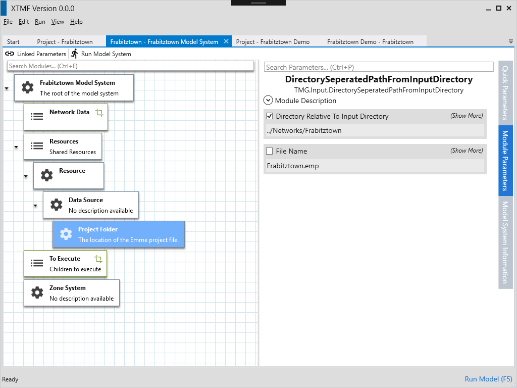
Parameter display for choosing a path to the Emme project folder, along with the project file name.
Under the To Execute module, add a new child module with the type Execute Tools From Modeller Resource. This allows us to begin calling tools that are defined
within Emme or any loaded toolbox. From resource indicates that we will use the Emme resource defined earlier under the “Resources” module. When the module is expanded, assign Resource Lookup to the Emme Modeller child module. Once added, assign the unique name entered previously as the Resource Name.
See also
For more information regarding resources and their usage please see Working with Resources.

Creating an Emme modeller resource.
